2.2.2.1. Pre-processing techniques for a dot-pattern image
Binarization
Dots are extracted from a calibration image by binarization (Fig. 2.2.2.1.1). Then the center-of-mass of each segmented dot is calculated and used as a reference-point.
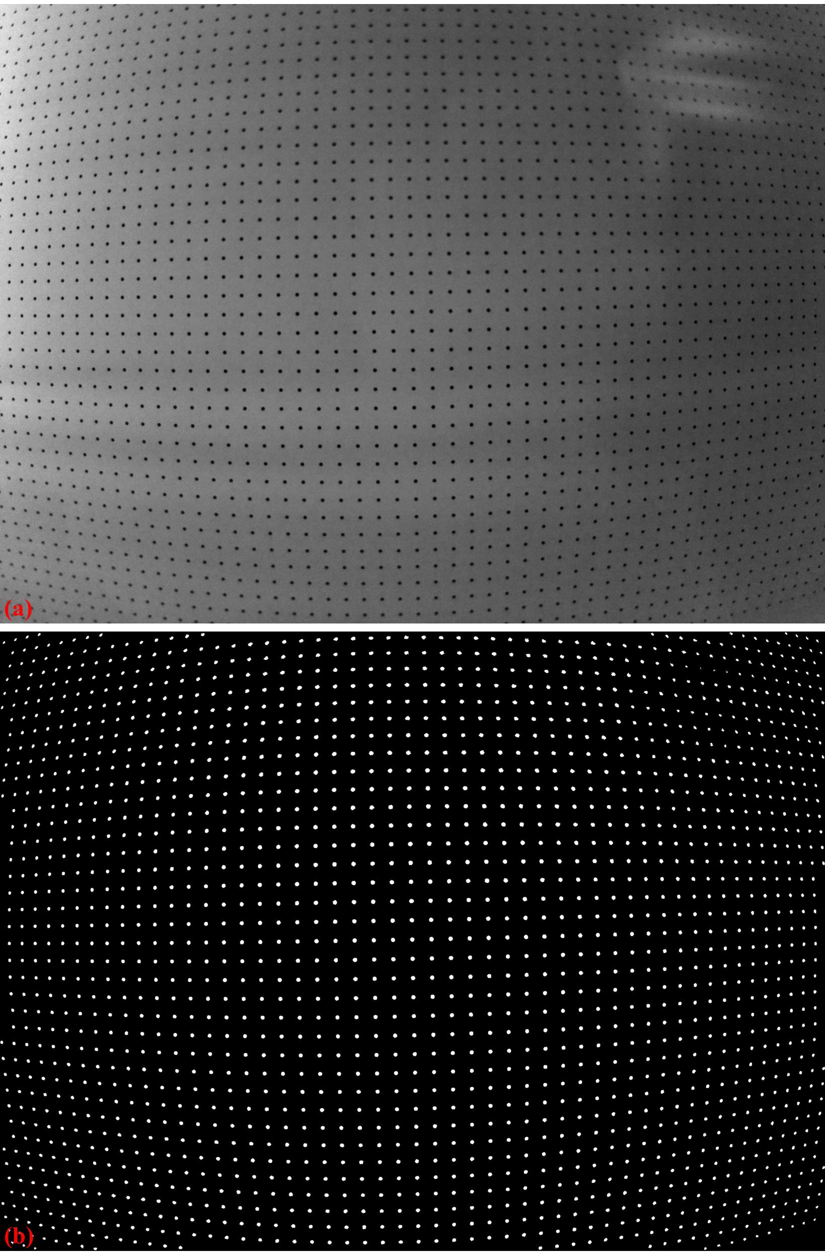
Fig. 2.2.2.1.1 Demonstration of the image binarization. (a) Dot-pattern image. (b) Segmented dots.
Normalizing background
The binarization uses a global thresholding method. In some cases, the background of an image is non-uniform which affects the performance of the thresholding method. Discorpy provides two ways of normalizing the background of an image: using a strong low-pass filter (Fig. 2.2.2.1.2) or using a median filter with a large-size window.

Fig. 2.2.2.1.2 Demonstration of background normalization. (a) Dot-pattern image (X-ray target). (b) Extracted background. (c) Corrected image.
Removing non-dot objects
Discorpy provides two methods for removing non-dot objects after a binarization step. In the first approach, the median size of dots (MS) is determined, then only objects with sizes in the range of (MS–R*MS; MS+R*MS) are kept where R (ratio) is a parameter. In the second approach, the ratio between the largest axis and the smallest axis of the best-fit ellipse is used. Objects with the ratios out of the range of (1.0; 1.0+R) are removed.
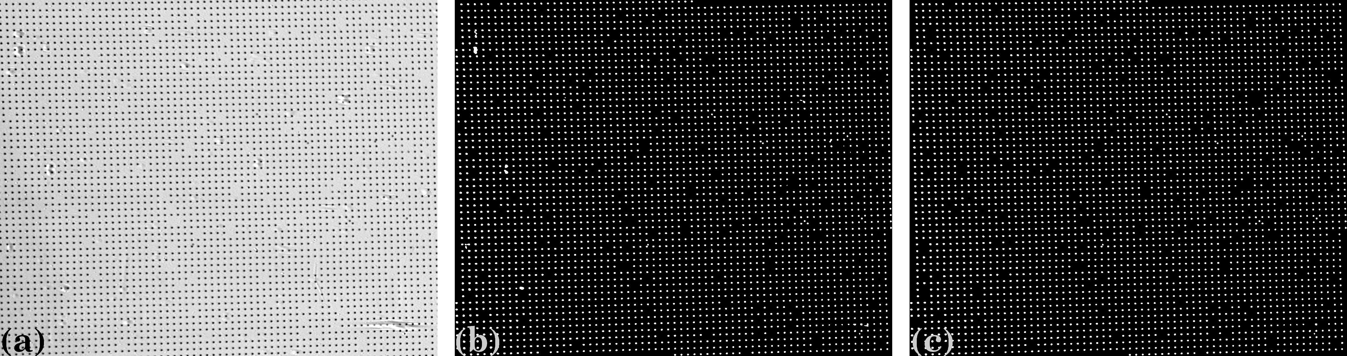
Fig. 2.2.2.1.3 Demonstration of removing non-dot objects.(a) Dot-pattern image (X-ray target). (b) Binary image. (c) Image with non-dot objects removed.
Removing misplaced dots
Custom-made dot-patterns may have dots placed in wrong positions as shown in Fig. 2.2.2.1.4. In Discorpy, a misplaced dot is identified by using its distances to four nearest dots. If none of the distances is in the range of (MD–R*MD; MD+R*MD), where MD is the median distance of two nearest dots and R is a parameter, the dot is removed. This method, however, should not be used for an image with strong distortion where the distance of two nearest dots changes significantly against their distances from the optical center. A more generic approach to tackle the problem is shown in section 2.2.3.
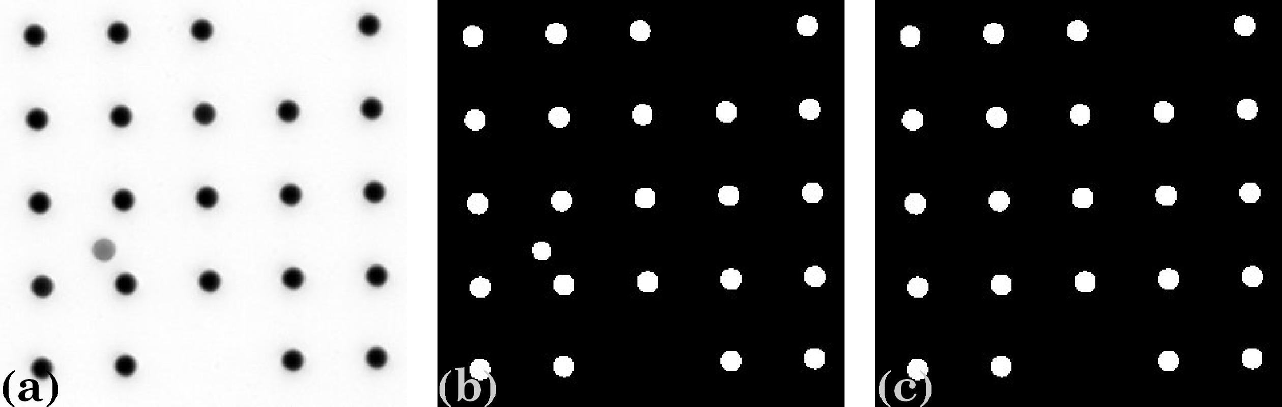
Fig. 2.2.2.1.4 (a) Image with a misplaced dot. (b) Binary image. (c) Image with misplaced dot removed.